

Like most pumps, the "similarity law" commonly used for calculating cutting at constant speed (should be "cutting law" - pump salon note 1)
cannot accurately reflect the relationship between changes in impeller diameter and the hydraulic performance achieved by the pump.
The calculation results usually indicate that there are more cuts that affect the required head and flow reduction than needed.
If the calculated cutting requires a diameter reduction of 10%, then only 7% or 8% should be reduced.
The lower the specific speed of the impeller design, the greater the difference. This topic is only covered in a few pump manuals.
Val Labanoff and Robert R. Ross provided a detailed introduction to this topic in their first edition of "Centrifugal Pumps - Design and Applications" on pages 18 and 19.
Like most pumps, the "similarity law" commonly used for calculating cutting at constant speed (should be "cutting law" - pump salon note 1)
cannot accurately reflect the relationship between changes in impeller diameter and the hydraulic performance achieved by the pump.
The calculation results usually indicate that there are more cuts that affect the required head and flow reduction than needed.
If the calculated cutting requires a diameter reduction of 10%, then only 7% or 8% should be reduced. The lower the specific speed of the impeller design, the greater the difference.
This topic is only covered in a few pump manuals. Val Labanoff and Robert R. Ross provided a detailed introduction to this topic in their first
edition of "Centrifugal Pumps - Design and Applications" on pages 18 and 19.
This depends on the specific speed of the impeller. Specific speed is an index related to pump performance at the maximum diameter impeller
and the flow rate at the optimal efficiency point at a given speed.
The specific speed index categorizes the hydraulic characteristics of pump impellers based on their type and proportion.
On this index, most refineries' pumps are between 900 and 2500 (the specific speed values in this article are in American units - pump salon note
2); Some vertical multi-stage pumps range from 4000 to 6000.
For radial design, the impeller diameter should not be reduced to more than 70% of the maximum design diameter.
The reduction of pump impeller diameter can also change the outlet channel width, blade outlet angle, and blade length, and may significantly reduce efficiency.
The more the impeller diameter decreases from the maximum diameter, the higher the specific speed
(rather than the suction specific speed), and the more the pump efficiency will decrease with the cutting of the impeller.
What effect does cutting the impeller have on the pump NPSHR?A small decrease in impeller diameter will only slightly increase NPSH. When the diameter decreases by 5% to 10%, NPSHR will significantly increase.
Not all pump companies consistently show an increase in NPSHR as the impeller diameter decreases on their pump curves.
When the margin between NPSHR and NPSHA is very small or the NPSHR of the pump is very low, this factor must be taken into account.
What effect does cutting the impeller have on axial vibration?Excessive clearance between the impeller cover plate and the pump casing and inlet reflux can cause eddy currents around the impeller, leading to low-frequency vibration.
In diffusers and volute pumps, there are always fluid disturbances related to inlet reflux and cavitation. As the diameter of the impeller decreases,
the flow distribution pattern on the outlet width of the impeller becomes more unstable.
The trend of high-pressure liquid returning to the low-pressure side and generating tip reflux greatly increases.
Similarly, pumps with higher energy levels are the main concern - pumps with a head exceeding 200 m (650 ft) per stage
and a power exceeding 225 kW (300 hp) per stage are considered high-energy pumps (pump salon note 3).
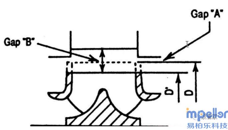
For many years, the tip of the volute or diffuser has been carefully machined to increase the gap B while maintaining the gap A
(the gap between the impeller cover plate and the pump casing is called the A gap,
and the gap between the impeller blade tip and the volute tongue is usually called the B gap - pump salon note 4),
in order to greatly reduce the frequency of blade vibration. By increasing the radial clearance B from 1% to 6%,
the pulsating hydraulic pressure acting on the impeller can be reduced by 80% to 85%.
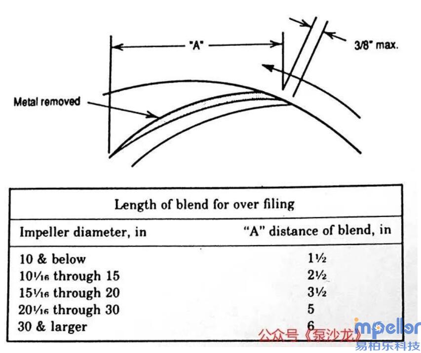
Figure 4: Filing the upper part of the impeller bladeThe slight improvement in efficiency is due to the reduction of various energy consumption phenomena,
such as high noise, impact and vibration caused by blade passage frequency, and stall (detachment) generated at the inlet of the diffuser.
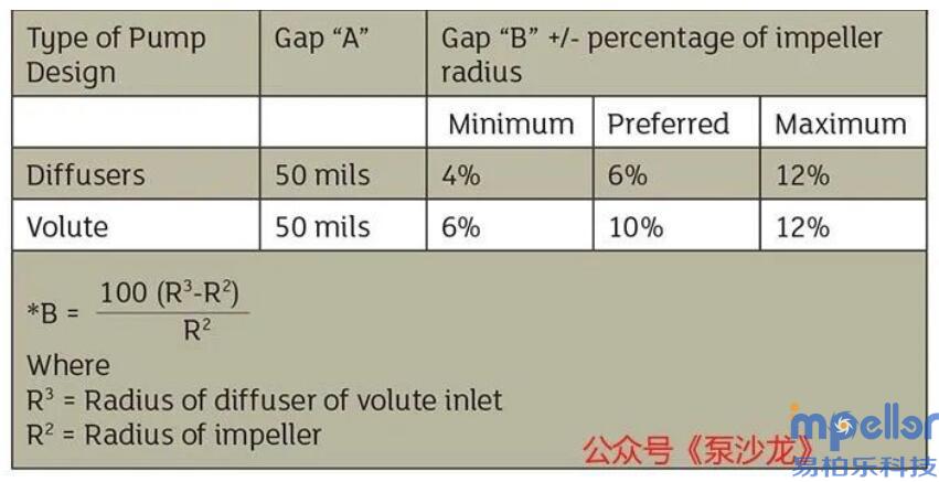
Table 1 provides Dr. Elemer Makay's recommended dimensions for the radial clearance between the pump impeller and the casing.
If the number of impeller blades is equal to the number of diffuser/volute blades, the radial clearance must be greater than approximately 4%.
Table 1: Recommended Pump Radial Clearances.The best method to cut the impeller?
What is the best method to cut the impeller from the maximum diameter to adjust the head and flow rate of a centrifugal pump?
Is it best to cut both the impeller blades and the cover plate at the same time or only the blades?
There are no strict guidelines for impeller cutting in terms of machinery, but there are several pump structure
and hydraulic design factors that need to be considered when deciding what to cut.
The cutting method of the impeller will greatly affect the hydraulic performance and vibration level of the pump.
Before deciding how to cut the impeller, please evaluate the hydraulic characteristics.
For volute pumps, the entire impeller, blades, and cover plate can be cut as shown in Figure 1.
However, in some pumps, this method can change the clearance A, resulting in uneven flow distribution in the impeller outlet area, leading to axial vibration and other problems.
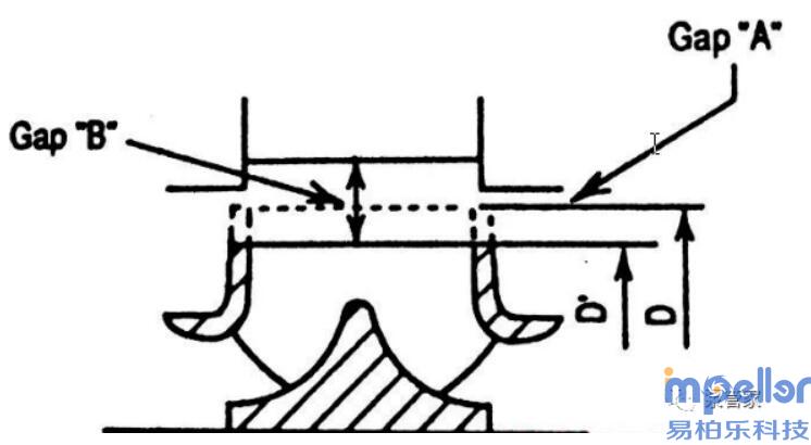
Double suction impeller pumps are particularly sensitive to problems caused by increasing clearance A,
so cutting the entire impeller is not a good choice. It is best to chamfer the impeller blades (see Figure 2) to keep the cover plate unchanged,
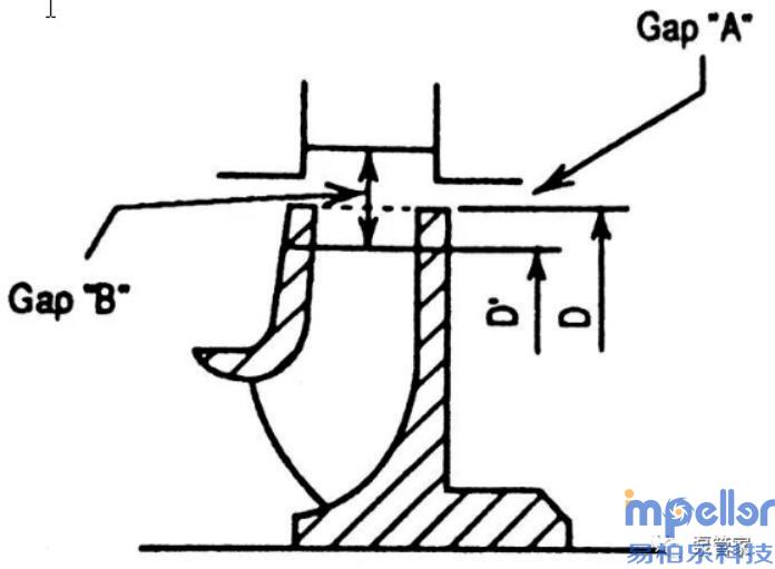
or only cut the blades (see Figure 3). Cutting the blades will only make the outlet flow pattern more uniform and reduce the reflux trend in the outlet area.
The clearance A (radial) should be approximately 0.050 inches (1.25 mm) to minimize vibration caused by blade passage frequency.
In most diffusion type pumps, it is best to only cut the blades (see Figure 3) to control the adverse effects of tip reflux and increased clearance A.
This cutting will produce a more stable head flow curve.
Uniform flow reduces the trend of tip backflow and greatly reduces the possibility of backflow in the outlet area.After a significant reduction in diameter, there may be too many unsupported cover plates left.
The inclined cutting keeps the cover plate unchanged, solves the structural strength problem, and improves the outlet flow pattern.
Sometimes, even if the distance between the outer diameter of the impeller blade and the volute tongue (clearance B) is correct,
an impeller with blunt blade tips will generate hydraulic "hammers" in the impeller outlet area and volute area, causing disturbance.
Figure 5: Sharpening of impeller blades
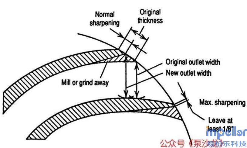
Filing on top: By "filing on top" to make the blade thinner or remove metal from the leading edge (working surface) of the blade,
this interference can be partially or completely eliminated (see Figure 4).
Another advantage of this technology is to restore the blade outlet angle to the angle close to the maximum impeller design (i.e., the angle before the diameter reduction).
File the bottom: Sharpening the lower side of the trailing edge (back of the blade) can expand the outlet area of the liquid flow channel (see Figure 5).
This usually results in a head increase of approximately 5% near the Best Efficiency Point (BEP), depending on the outlet blade angle.
At least 1/8 inch (3 mm) of blade tip thickness must be left. Sharpening the blades can also slightly improve efficiency.
In high pressure situations, it is necessary to carefully sharpen the blades, as they are under high static and dynamic stress.
Author Introduction: Ed Nelson is a consultant in the turbomachinery and rotating equipment industry.Name: Ben
Mobile:86 137 0588 0773
Tel:86 137 0588 0773
Whatsapp:8613705880773
Email:info@ssimpeller.com
Add:No. 25, Lane 7488, Hutai Road, Jiading District, Shanghai


